平衡小车
大三才做出来平衡小车实在是太菜了…分享一下过程和学习笔记。写这篇时还没有学过任何控制相关的课程,如有错误请见谅
平衡小车 PID 原理
PID
网上有太多 PID 解析了,这里不多赘述,讲一下我的理解
小时候一定拨过钢尺,振幅越来越小最后不振了。能来回振是因为钢尺有弹性,能停下是因为有阻尼。弹簧 + 阻尼一般能解决大部分问题,而这其实就是 PD 控制器。二阶线性微分方程从原理上解释了这一切。忘光了现学的…
$$ my’’+cy’+ky=f(t) $$
用 RLC 电路理解也可以
假设这些参量均大于零,即特征方程的解$r_1 , r_2$的实部$\frac{-c}{2m}$小于零,则微分方程的通解$y=K_1 e^{r_1 t} + K_2 e^{r_2 t}$一定收敛。理想情况是临界阻尼$r_1 = r_2$, 此时通解为$y=Ke^{rt} + Kte^{rt}$
因此,PD 控制器可以理解为给原本的模型套上了弹簧和阻尼来使它稳定。然而,对于有某些固定载荷的情况,被控量最终会根据 P 稳定在某个偏离目标量的地方。积分项 I 的引入就是为了消除这种稳态误差。
姿态环
将小车当前的倾角作为 PD 控制器的输入,这里注意各参数的符号。小车前倾,我们就向前加速赶一步,后倾就向后加速。但这种控制方法并不稳定,即便参数调试得非常好,最后小车总是加速向一侧倒下。这是因为电机速度具有上限。当小车姿态已经归中但底盘仍有速度时,因为比例部分几乎为零,电机输出一个极小值,产生近似刹车的效果,使得小车快速点头,反而可能产生了比一开始更大的倾角。
速度环
为了解决这个问题,我们引入了速度环。速度环以车轮转速为输入,其输出作为姿态环的目标位置输入,即小车有前向的速度时,将姿态环的零位调整到一个后倾的角度,让姿态环多赶一步。姿态环采用 PD,速度环采用 PI. 两套控制参数的调试还是有点麻烦,理想过程是先调姿态 P 到一个不错的响应,再调姿态 D 到能够站立一小会儿,再调速度环。
中断引发的故事
树莓派
我总觉得 arduino 更像个玩具,买了没啥大用,而树莓派也有 GPIO 口,还是个 Linux PC,怎么看可玩性都更高一些。于是买了个最丐的 2G RAM 4B 进行开发。主要使用 C 语言和 Wiring Pi. 硬件部分淘宝解决,上来先驱动下各个部件:
- 直流电机
驱动器是常见的 L298N. 简单说就是两个引脚电平调方向,一路 PWM 输出控制电压。PWM 采用树莓派的 pwm0, pwm1 两路硬件 pwm, WiringPi 有对应的函数,非常好写,注意一下引脚号即可。 - MPU6050
I2C 协议的六轴陀螺仪加速度计。MPU6050 有内置的运动处理器 DMP,可以直接以四元数的形式输出融合后的姿态,诶!?什么叫融合…直接读不就完了?节约主机计算资源,不过不能通过一般的方式驱动,芯片手册里也没有驱动相关的信息。官方提供了 MSP430 上的例程,代码量比较大,核心是要传一串神秘代码来开启 DMP 功能。我找了半天适合树莓派的 dmp 库只发现了这个 C++ 库. 虽说也可以自行移植,但当时我这个小白办不到啊… 唉,在 C++ 里写 C 吧。 - 编码器
硬件上它产生两路 90° 相位的方波,每转一圈会产生固定数量的跳变。通过读一路跳变时另一路的电平来确定当前旋转方向,往往用中断驱动。真是神奇啊。
WiringPi 包装了方便的函数来让我们注册中断处理函数:
int wiringPiISR (int pin, int edgeType, void (*function)(void)) ;这里只需要传入函数指针,即可在中断发生时调用注册的函数。注意这个函数的返回值和参数都是void, 那么怎么与外界联系呢?答案是使用全局变量:
long long COUNT;
void myISR(void);

void myISR(void){
    COUNT++;
}

int main(void){
    wiringPiSetup();
    /* Some code */
    wiringPiISR(pin, INT_EDGE_BOTH, myISR);
    /* Some code */
}
这样,每次中断发生时,COUNT 的值都会自增。因为编码器计数非常快,这里把 COUNT 定义为 long long (64 位)
贴一下我的 C 代码,成功驱动了电机和编码器吗?, 还可以在 SSH 中按q退出,可以说距离完成只差控制部分了:
motor.h
#include <pthread.h>
#include <stdbool.h>
#include <stdlib.h>
#include <unistd.h>
#include <wiringPi.h>

#define PIN_MOTOR1 26
#define PIN_MOTOR1_IN1 6
#define PIN_MOTOR1_IN2 27
#define PIN_MOTOR1_OUT1 28
#define PIN_MOTOR1_OUT2 29
#define PIN_MOTOR2 23
#define PIN_MOTOR2_IN1 22
#define PIN_MOTOR2_IN2 21
#define PIN_MOTOR2_OUT1 24
#define PIN_MOTOR2_OUT2 25
#define START_POWER 120

typedef struct smotor {
  const short PIN;
  const short PIN_IN1;
  const short PIN_IN2;
  const short PIN_OUT1;
  const short PIN_OUT2;
  const short DIR;
  const void (*run)();
  const int (*readSpd)();
  long long lastPos;
} Motor;

int motorInit(void);

static void motor(Motor *pmotor, int power);
static int readSpd(Motor *);
static void readEnc1A(void);
static void readEnc1B(void);
static void readEnc2A(void);
static void readEnc2B(void);

Motor leftWheel;
Motor rightWheel;
motor.c
#include "motor.h"

int motorInit(void) {
  if (!wiringPiSetup()) {
    /* set interrupt response */
    wiringPiISR(PIN_MOTOR1_OUT1, INT_EDGE_BOTH, &readEnc1A);
    wiringPiISR(PIN_MOTOR1_OUT2, INT_EDGE_BOTH, &readEnc1B);
    wiringPiISR(PIN_MOTOR2_OUT1, INT_EDGE_BOTH, &readEnc2A);
    wiringPiISR(PIN_MOTOR2_OUT2, INT_EDGE_BOTH, &readEnc2B);
    /* set pin mode */
    pinMode(PIN_MOTOR1, PWM_OUTPUT);
    pinMode(PIN_MOTOR1_IN1, OUTPUT);
    pinMode(PIN_MOTOR1_IN2, OUTPUT);
    pinMode(PIN_MOTOR1_OUT1, INPUT);
    pinMode(PIN_MOTOR1_OUT2, INPUT);
    pinMode(PIN_MOTOR2, PWM_OUTPUT);
    pinMode(PIN_MOTOR2_IN1, OUTPUT);
    pinMode(PIN_MOTOR2_IN2, OUTPUT);
    pinMode(PIN_MOTOR2_OUT1, INPUT);
    pinMode(PIN_MOTOR2_OUT2, INPUT);

    return 0;
  } else {
    return -1;
  };
};
void motor(Motor *pmotor, int power) {
  digitalWrite(pmotor->PIN_IN1, ((power * pmotor->DIR) > 0));
  digitalWrite(pmotor->PIN_IN2, ((power * pmotor->DIR) < 0));
  pwmWrite(pmotor->PIN, abs(power) + START_POWER);
};
int readSpd(Motor *pmotor) {
  long long pos = pmotor->lastPos;
  usleep(5000);
  return (pmotor->lastPos) - pos;
};

void readEnc1A(void) {
  (leftWheel.lastPos) -=
      leftWheel.DIR *
      (((digitalRead(PIN_MOTOR1_OUT1) == digitalRead(PIN_MOTOR1_OUT2)) << 1) -
       1);
  /* equivalent to
  (motor1.lastPos) += motor1.DIR * ((digitalRead(PIN_MOTOR1_OUT1) ==
  digitalRead(PIN_MOTOR1_OUT2)) ? -1 : 1);
  */
};
void readEnc1B(void) {
  (leftWheel.lastPos) +=
      leftWheel.DIR *
      (((digitalRead(PIN_MOTOR1_OUT1) == digitalRead(PIN_MOTOR1_OUT2)) << 1) -
       1);
};
void readEnc2A(void) {
  (rightWheel.lastPos) -=
      rightWheel.DIR *
      (((digitalRead(PIN_MOTOR2_OUT1) == digitalRead(PIN_MOTOR2_OUT2)) << 1) -
       1);
};
void readEnc2B(void) {
  (rightWheel.lastPos) +=
      rightWheel.DIR *
      (((digitalRead(PIN_MOTOR2_OUT1) == digitalRead(PIN_MOTOR2_OUT2)) << 1) -
       1);
};

Motor leftWheel = {
    PIN_MOTOR1,      PIN_MOTOR1_IN1,  PIN_MOTOR1_IN2,
    PIN_MOTOR1_OUT1, PIN_MOTOR1_OUT2, .DIR = 1,
    motor,           readSpd,         .lastPos = 0,
};
Motor rightWheel = {
    PIN_MOTOR2,      PIN_MOTOR2_IN1,  PIN_MOTOR2_IN2,
    PIN_MOTOR2_OUT1, PIN_MOTOR2_OUT2, .DIR = -1,
    motor,           readSpd,         .lastPos = 0,
};
main.c
#include "motor.h"
#include <stdio.h>

void *usrInterrupt(void *arg);

char usrInput = ' ';

int main(void) {
  if (!motorInit()) { // PIN Definition
    /* set high priority  */
    piHiPri(10);
    pthread_t th_usr_interrupt;
    char *th_usr_interrupt_arg = &usrInput;
    if (pthread_create(&th_usr_interrupt, NULL, usrInterrupt,
                       th_usr_interrupt_arg)) {
      return -1;
    }

    int t0 = millis();
    while (usrInput != 'q') {
      leftWheel.run(&leftWheel, 500);
      rightWheel.run(&rightWheel, 500);
      printf("%lli|%lli\n", leftWheel.lastPos, rightWheel.lastPos);

      delay(100);
    };
    pthread_detach(th_usr_interrupt);

    /* turn off all outputs */
    pwmWrite(PIN_MOTOR1, 0);
    pwmWrite(PIN_MOTOR2, 0);
    digitalWrite(PIN_MOTOR1_IN1, LOW);
    digitalWrite(PIN_MOTOR1_IN2, LOW);
    digitalWrite(PIN_MOTOR2_IN1, LOW);
    digitalWrite(PIN_MOTOR2_IN2, LOW);

    printf("Done!\n");
  }
  return 0;
};

/*------------ threads --------------*/
void *usrInterrupt(void *arg) {
  printf("Type in 'q' to quit.\n");
  while (*(char *)arg != 'q') {
    scanf("%c", arg);
  };
};
因为上文提到的 MPU6050 的 DMP 问题,我准备迁移到 C++, 正好也准备学一学 C++. 于是看了几天菜鸟教程,自信已经有了 C with class 的水平。我定义了一个电机类 Motor 代码不忍直视就不贴了: 成员有驱动电机的各引脚short pin_x, 编码器计数long long pos, 电机速度int spd, 驱动函数void Motor::run(int pow), 以及编码器中断发生时修改编码器计数的成员函数void Motor::enc(int phase). 为了限制访问,能私有的我都定义成了 private 真是年轻啊啊啊 (捂脸; 还定义了一个底盘类 Base, 成员有两个电机实例和一个 MPU6050 实例。因为 Motor 类成员都是私有的,还费劲定义了一番友元类友元函数等等,以便编码器读速度的线程可以访问到电机实例。保险起见,还用int piHiPri (int priority)把测速线程调到了最高优先级
一番忙活下来,终于能编译了。卧槽!? 编码器竟然会时不时抽风!即便电机不动也会乱跳数字。最奇葩的是这个 bug 竟然不能稳定复现… 我百思不得其解。鉴于编码器是速度环的基本,这个问题没解决,后面的部分也无法开展… 这个问题真是让我毫无头绪,毕竟原理上这份 C++ 版本和之前的 C 版毫无差别。苍蝇乱撞一天后,我…放弃了…
不过我隐约觉得问题可能在我套的这么多层抽象上
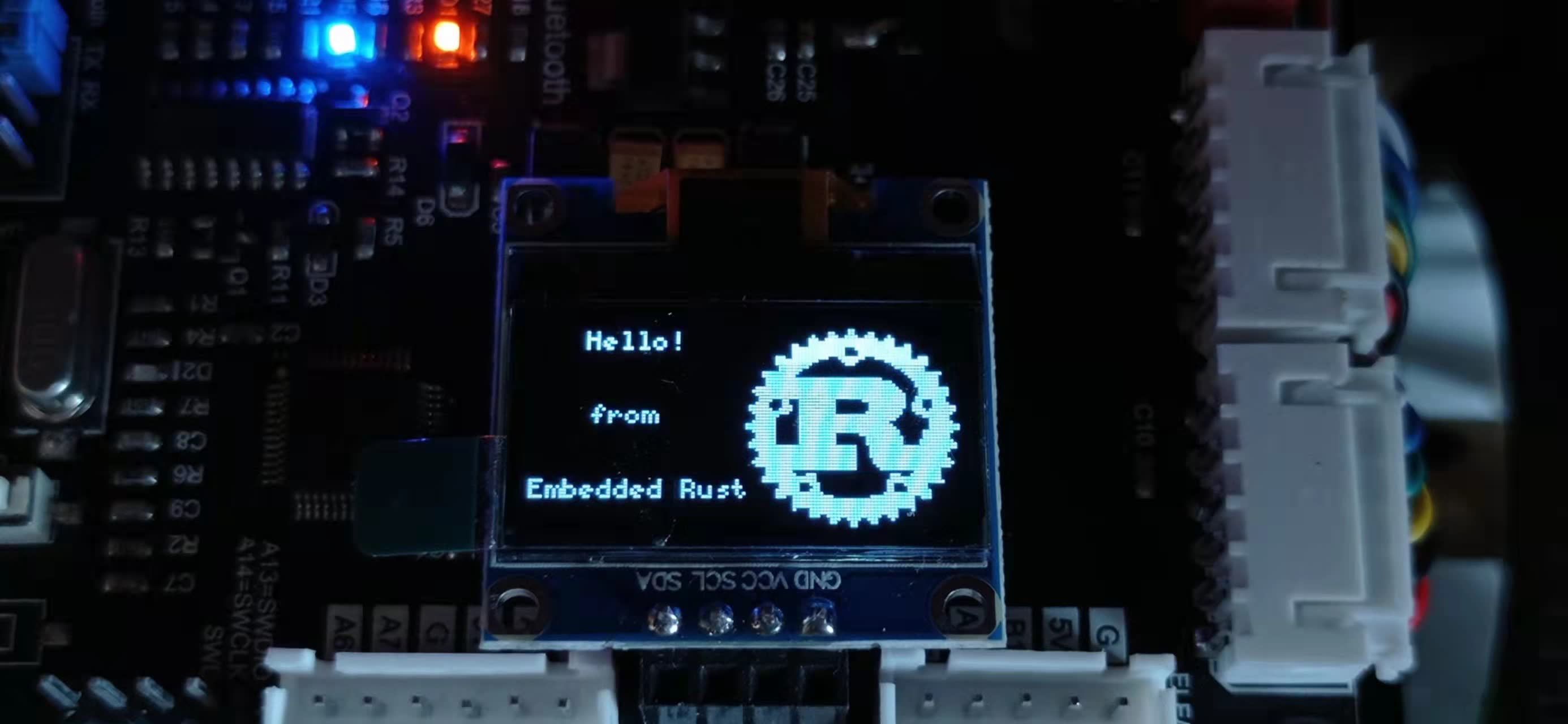
Rust 与并发编程
假期短暂,我的第一次尝试以失败告终。之后在网课之余,机缘巧合,我接触到了 Rust 这门语言。简单看了看 the book 发现还不错,于是花了三周多,在网课之余把它看完了。其中 ownership 和 borrow checker 非常特别,它们规定:
对一个变量的引用 (指针), 只能存在:
- 有且仅有一个独占引用(写者), 且没有共享引用 (读者), 或
- 没有独占引用 (写着), 任意多个共享引用 (读者)
换句话说,只要有人在写,其他任何读写操作都不能进行。等等,我之前的编码器计数是怎么实现的?违背了这个规范呀!
一年后的今天,让我们彻底了结这个问题:数据争用. 我用的 Raspbian 是 32 位版本,其 long long 被定义为 64 位有符号整型。换句话说,绝大部分对 64 位整数的操作都不能在一条汇编指令中完成。因此,当测速线程修改了速度变量却还没完成时,有可能被调度打断 (raspbian 并不是实时系统). 此时读取这个变量就会发生数据争用的问题。至于 C 代码为什么没问题,是因为仅仅打印了编码器计数,而没有另起一个测速线程。中断处理速度极快且不会被其他线程抢占,而中断发生的频率又没有高到能够常常打断主线程中的读取过程。我翻 makefile 才发现我 C 开了 O3, C++ 啥优化也没开…
那么,合理的解决办法是什么呢?
- 原子操作
atom 是不可分的意思,原子操作就是不会被打断的操作。缺点是需要处理器支持,且一般只能操作长度不大于处理器字长的数据类型。关于Ordering的选择,如果只需要原子性,使用Ordering::Relax即可,用于计数的话再适合不过了。在多核情况下还需要考虑内存一致性来选择 Ordering, 最严格的一般是Ordering::SeqCst. - 互斥锁\读写锁 (普通线程)
对于有操作系统 (包括实时系统) 情况下普通线程间的资源共享,可以使用这两种锁。详见 the book. 如果获取锁失败,线程可以选择出让控制权让操作系统先调度其他线程。 - 临界区 (中断)
由于中断总能抢占当前线程,除非你允许中断处理函数在资源被占用的情况下漏掉中断不处理,否则主线程中的锁形同虚设。有的处理器可以暂时关闭所有中断,这样当前正在执行的任务就不会被打断。如果使用 rust,还需要配合Mutex,RefCell等来通过语法检查,详见 the embedded rust book. - 缓冲区
还有一种取巧的做法,使用内存来通信。环形缓冲区可以实现为数组 + 头尾原子指针,我们可以让发送端独占头指针,接收端独占尾指针,每次发送/接收,都向内存中写入/读取数据后操作指针自增。只要缓冲区够大且接收端处理速度大于发送端发送速度,一般不会漏掉消息。保险起见还可以在发送和/或接收时加上头尾指针判断
如果现在让我重新设计树莓派编码器测速逻辑:我会使用中断操作原子类型计数,用互斥锁包装速度全局变量,让测速线程和主线程抢锁,来保证对速度变量的操作不会产生竟态条件。
不过,后来实习接触了 STM32 这样的单片机,拿来做平衡小车足够了,反观树莓派 4B 还需要 5V3A 供电,我还特意买了微雪的电池扩展版,头顶两节 18650 简直不要太笨重,于是树莓派就光荣的吃灰了。STM32 的定时器具有编码器功能,可以通过每次读取后清零的方法获取速度,配合定时器中断测速即可。不过我用 rust 实现的版本因为软件 I2C 的库必须要一个定时器,导致没定时器拿来做中断了… 只好用延时实现。
多传感器融合
还记得 MPU6050 有个 DMP 库吗?后来转向 Rust + STM32 后,因为没找到能用的 DMP 库,我就用的六轴原始数据。确定角度还不简单?三轴加速度和重力一比较就完事儿了,我用的库还有现成的包装 get_acc_angles(&mut self) -> Result<Vector2
快快拿来一试,再加上现成的 PID 库, P 输入用刚才获得的角度,D 输入直接用陀螺仪,不到一个小时代码就编译通过了。不得不说,Rust 这点真的香:99% 的情况下能过编译就能跑. 小车拿在手里,前倾就向前加速,后倾就向后加速,各参数极性正确!但是 PID 参数我竟然调了三天都没调明白…连最基本的姿态环都几乎无法实现。最好的一组参数也只能维持个 10 秒钟左右。我干脆两手捏住轮子当成纯倒立摆,诶!?怎么这都稳定不了?看了输出才发现,获取到的角度抖动太大!那就加平滑滤波!可加了滤波也没法稳定,这让我又犯了难…
想想也是,这小车本身就在抖动,读出来的加速度可不仅仅是重力加速度。那要怎么确定角度呢?有以下几种办法:
互补滤波
$$ \theta = k \cdot \theta_{\text{acc}} + (1-k)\cdot \int{{\omega}dt} $$
通过对读取到的角速度 $\omega$ 积分,我们也可以得到一个角度数据 $\theta_\text{gyro}$. 当然这个数据会因为累加存在一定的误差。之前提到从加速度计和重力方向也可以得到一个角度数据 $\theta_\text{acc}$, 我们把两个数据分辨乘以一定的权重后相加,作为上述控制系统的输入。在实际实现时,往往采用递推的方式将其改写为:
$$ \theta_{i+1} = k \cdot \theta_{\text{acc}} + (1-k)\cdot ({\theta_{i} + \omega dt}) $$
还可以根据当前两个数据的大小来动态调整权重,比如:当加速度计测到一个较大数据时,更相信陀螺仪。当陀螺仪数据很小时,更相信加速度计。
本来想用 Rust 在 STM32 上实现互补滤波的,但因为之前提到的定时器不够只能在 main 函数中 delay 测速来完成整个控制循环,实践发现这个延时并不稳定,导致陀螺仪积分要乘的 $dt$ 不好确定。最后还是决定转回 C,有 DMP 不用,何苦呢。
卡尔曼滤波
久仰卡尔曼滤波大名,可惜我水平不够还没看明白原理… 如果有现成的库可以使用,自然是拿来主义。我尝试了 rust 的 adskalman, 但因为编译出的二进制太大没能成功烧录。
关于卡尔曼滤波的原理,希望自己以后可以补充完全。
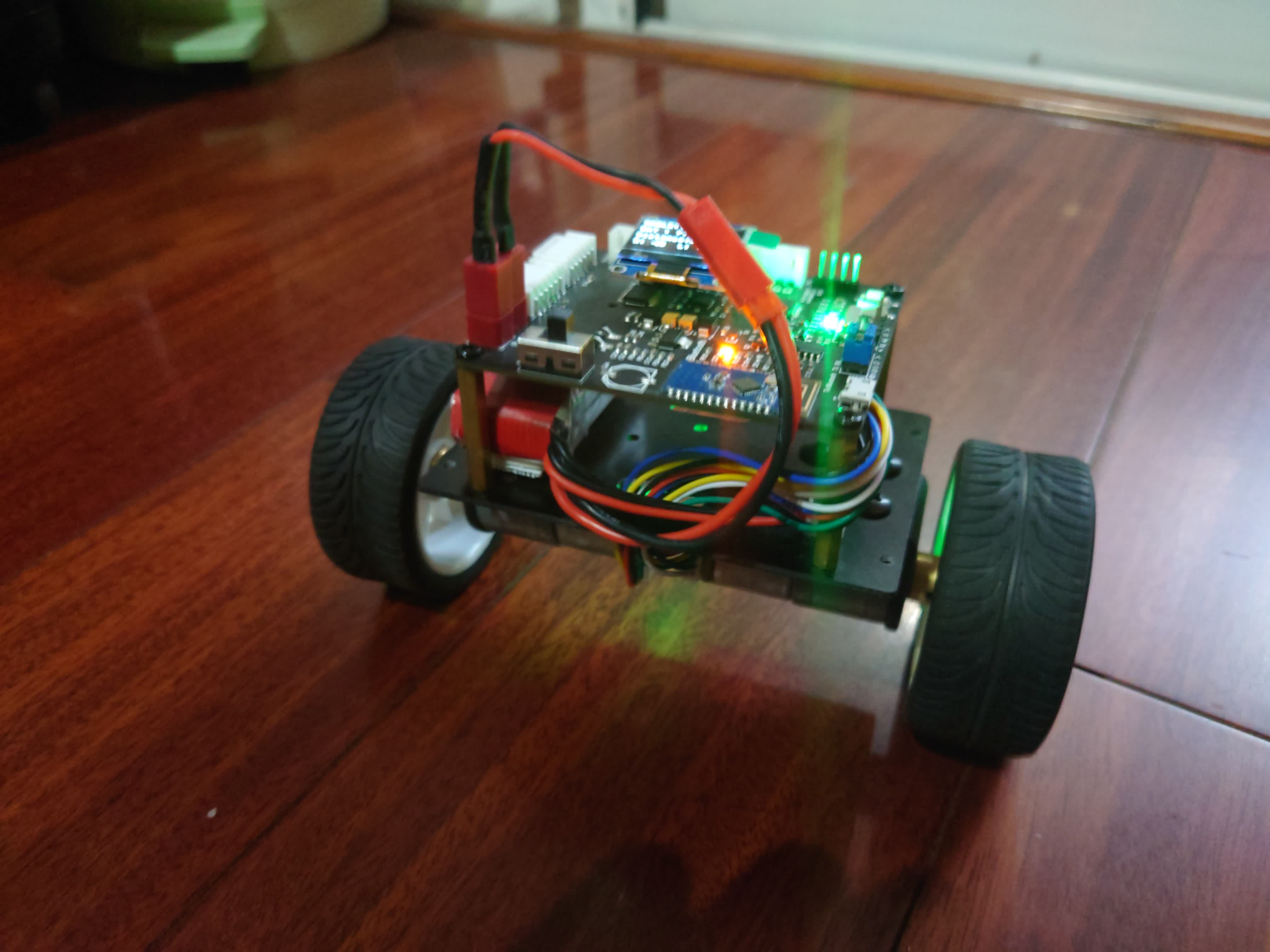
总结
最后用 C 和 DMP 完成的版本效果如下。时间紧张,代码质量太差,就不献丑了。
平衡小车,搞明白原理其实并不难。如果我一上来就选了 arduino,或许就不会接触到 Rust 和 STM32. 从树莓派一路踩坑下来,反倒收获了更多的知识和经验。